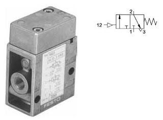
To support the directional control valves at the processing level, there
are various elements which condition the control signals for a task. The
elements are:
- Dual pressure valve (AND function)
- Shuttle valve (OR function)
A shuttle valve permits the combination of two input signals into an OR
function. The OR gate has two inputs and one output. An output signal is
generated, if pressure is applied at one of the two inputs.
The further development of processing elements in pneumatics has
brought about the modular systems, which incorporate directional control
valve functions and logic elements to perform a combined processing
task. This reduces size, cost and complexity of the system.
Friday, 30 July 2010
Combination valves
The combined functions of various elements can produce a new function.
An example is the time delay valve which is the combination of a
one-way flow control valve, a reservoir and a 3/2-way directional control
valve.
Depending on the setting of the throttling screw, a greater or lesser
amount of air flows per unit of time into the air reservoir. When the necessary
control pressure has built up, the valve switches to through flow.
This switching position is maintained for as long as the control signal is
applied.
Other combinational valves include the
- Two-hand start unit
- Pulse generator
- Stepper modules
- Memory modules
Pressure control valves
Pressure control valves are utilised in pneumatic systems. There are
three main groups:
- Pressure limiting valves
- Pressure regulating valves
- Pressure sequence valves
The pressure limiting valves are utilised on the up-stream side of the
compressor to ensure the receiver pressure is limited, for safety, and
that the supply pressure to the system is set to the correct pressure.
The pressure regulating valve keeps the pressure constant irrespective
of any pressure fluctuations in the system. The valve regulates the pressure
via a built-in diaphragm.
The pressure sequence valve is used if a pressure-dependent signal is
required for the advancing of a control system.
When the applied control signal reaches the set pressure, the 3/2-way
valve incorporated at this point is actuated. Conversely, the valve reverses,
if the control signal falls below the set pressure.
Flow control valves
The flow control valve restricts or throttles the air in a particular direction
to reduce the flow rate of the air and hence control the signal flow. Ideally
it should be possible to infinitely vary the restrictor from fully open to
completely closed. The flow control valve should be fitted as close to the
working element as is possible and must be adjusted to match the requirements
of the application. If the flow control valve is fitted with a
check valve then the function of flow-control is unidirectional with full free
flow in one direction.
Non-return valves
The non-return valve allows a signal to flow through the device in one
direction and in the other direction blocks the flow. Amongst others, this
principle is applied in shuttle valves or quick exhaust valves. The nonreturn
valve in the form of a basic element of other valve types is shown
in a broken outline in the illustration below.
- Check valve.
- Shuttle valve.
- Dual-pressure valve.
- Quick exhaust valve.
Directional Control Valves
The directional control valve controls the passage of air signals by generating,
cancelling or redirecting signals.
The valve is described by:
Number of ports or openings (ways): 2-way, 3-way, 4-way, etc.
Number of positions: 2 positions, 3 positions, etc.
Methods of actuation of the valve: manually actuated,mechanically actuated,pneumatically actuated,electrically actuated.
Methods of return actuation: Spring return, air return, etc.
As a signalling element the directional control valve is operated for example,
by a roller lever to detect the piston rod position of a cylinder.
As a processing element the directional control valve redirects or cancels
signals depending on the signal inputs received.
As a control element the directional control valve must deliver the required
quantity of air to match the power component requirements.
Pneumatic Valves
The function of valves is to control the pressure or flow rate of pressure
media. Depending on design, these can be divided into the following
categories:
Directional control valves
– Input/signalling elements
– Processing elements
– Control elements
Non-return valves
Flow control valves
Pressure control valves
Shut-off valves
Look at next video to know how valves works
media. Depending on design, these can be divided into the following
categories:
Directional control valves
– Input/signalling elements
– Processing elements
– Control elements
Non-return valves
Flow control valves
Pressure control valves
Shut-off valves
Look at next video to know how valves works
Subscribe to:
Posts (Atom)